Case Study: FRP Design Offers Seismic Adaptability
| TECHNICAL DATA |
|---|
| Product: Cable Bus Support Structure and Multi-Story Maintenance Access Platform |
| Process: Pultrusion, Fabrication |
| Materials & Sizes: EXTREN® Structural Shapes:
|
| For: Frost Engineering & Consulting |
| User: Data Center in Santa Clara, California |
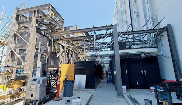
A data center equipment yard in Santa Clara, California required an extensive cable bus support structure and a multi-story maintenance access platform to service and maintain key equipment integral to the operation of the zero-downtime essential facility. Steel was originally planned for this massive, intricate, structure; however, the design would have required sourcing almost half a million pounds of structural steel to transport, fabricate and erect with an aggressive construction schedule, scarce supply of skilled labor and challenging site access restraints given the weight of key steel members.
Outfitted with these severe time, labor, and space constraints, the owners of the data center looked to Frost Engineering & Consulting to design an efficient, fast-erecting, non-steel structure capable of withstanding high seismic conditions within a densely populated area. Weighing in at 120,000 lbs. of FRP (versus 400,000 lbs. of the original steel structure), this 7,000 square foot dual-purpose exterior structure offers a 3,400 square foot cable bus support over one floor level and serves as a 3,600 square foot 2-story generator access platform.
Here are four of the more unique design challenges faced by the design team:
- Project Schedule:
Difficulties in sourcing raw materials, supply chain disruptions and the need for post-fabrication weatherproofing (galvanization) prohibited steel from being an effective solution for this project. The value-engineered FRP solution was designed, fabricated and fully erected prior to the anticipated delivery date of the first steel shipment. One of the key benefits noted by the installer was the reduced weight of the main structural components (averaging 60%-70% reduction in weight). This weight savings provided much more maneuverability, eliminated the need for heavy equipment and greatly accelerated the erection timeline. - High Seismicity:
This FRP structure represents the third heaviest free-standing FRP structure created to date and the largest all-FRP structure built in a high seismic region. The Owner also requested the structure be categorized as an essential facility (risk category IV) mandating the design team to accommodate a 1-in-2,500 year seismic event, including all seismic overstrength factors and elevated importance factors. State of the art ACMA seismic design standards were implemented in conjunction to finite element analysis (FEA) modeling to the acceptance of owner and regulatory bodies. - Prying Action:
Given the large magnitude of lateral demands and lack of diaphragm system, the majority of FRP beams were subject to varying degrees of axial loading. The prevalence of beam-axial demands required the Design Team address the implications of prying action on FRP connection elements. Taking inspiration from the AISC Steel Construction Manual equations (and other white papers on the subject) Frost Engineering & Consulting developed a closed-form FRP specific prying capacity equation to characterize the performance of typical beam end connections. - Elevated Temperatures:
Key coordination and design considerations were able to address the concerns of the generators' dynamic range of exhaust temperature output, at times approaching 800 degrees Fahrenheit.
All parties involved were pleased with the project from start to finish such that the owner has chosen FRP as the preferred material solution during future phases of the project. It is also noteworthy to mention that this project was awarded the 2021 Award for Composites Excellence for Most Creative Application of Composites. Click Here to see the presentation.
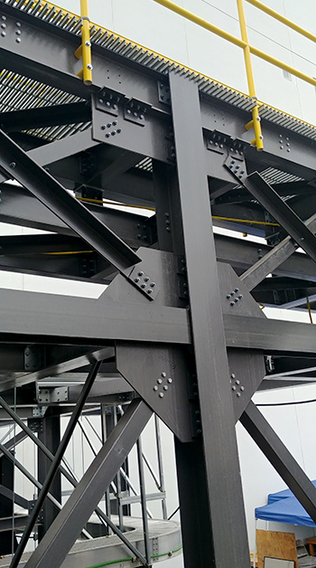
FRP Structural Connections and Technical Design
Using extensive Building Information Modeling (BIM) during layout of the structure, Frost Engineering & Consulting was able to model the structural connections in sufficient detail to accommodate installation clearances as small as 1/8”. The three most common connection types deployed for this project were:
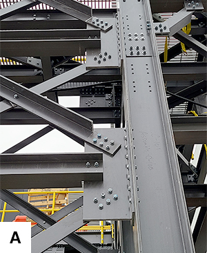
- WT Shape gusset (Figure A) used primarily in medium-duty vertical braced frames
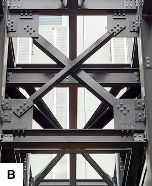
- Traditional gusset plates (Figure B) used primarily in heavy-duty vertical braced frames
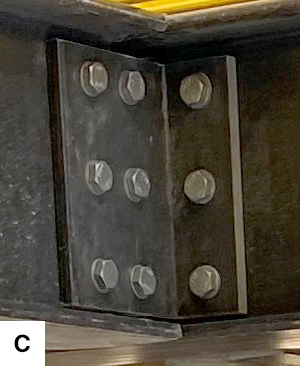
- Double clip angles (Figure C) used for typical beam end connections
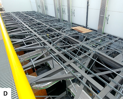
The cable bus structure (Figure D) contains vertical bracing only in E-W direction and utilizes a system of horizontal bracing to drag lateral forces in the N-S direction to the lateral force elements of the generator platform. The generator platform (Figure E) contains vertical bracing in both primary directions utilizing portal frames and knee-braced frames as required to maintain walkway clearances.

You must be logged in to post a comment.